Description
4-20mA Loop Simulator Generator Testing
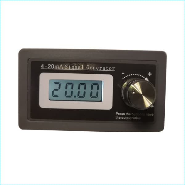
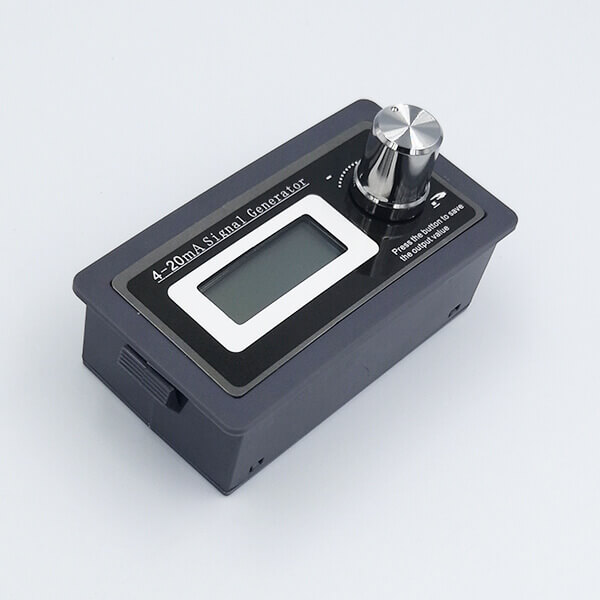
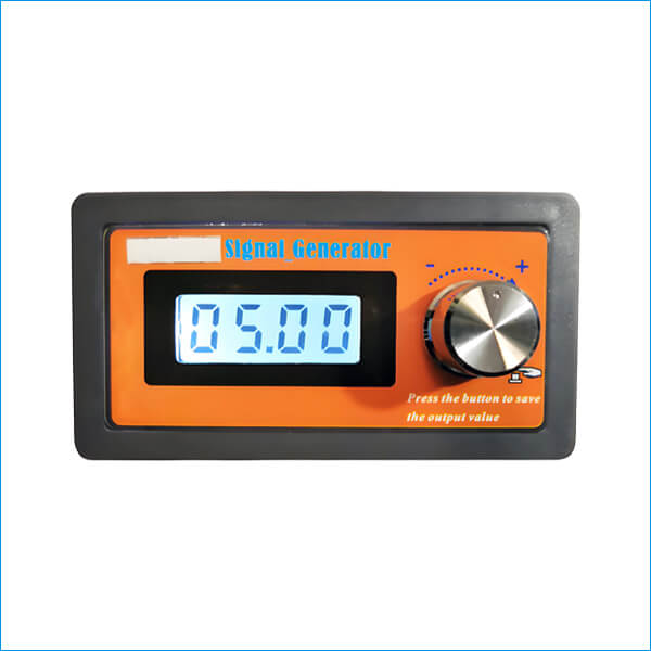
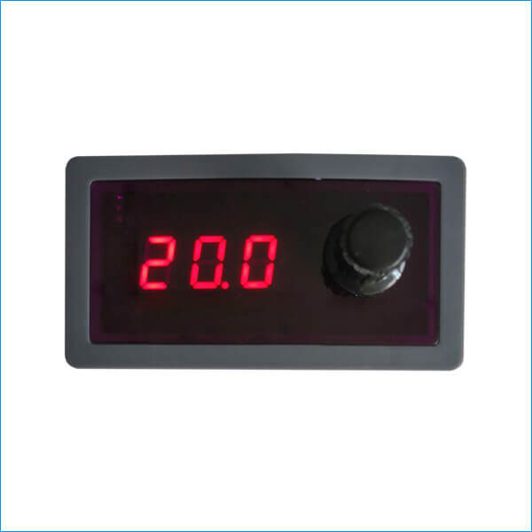
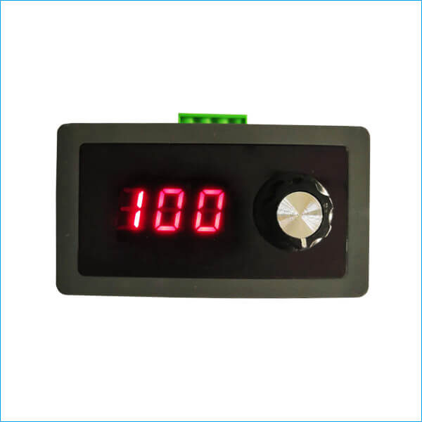
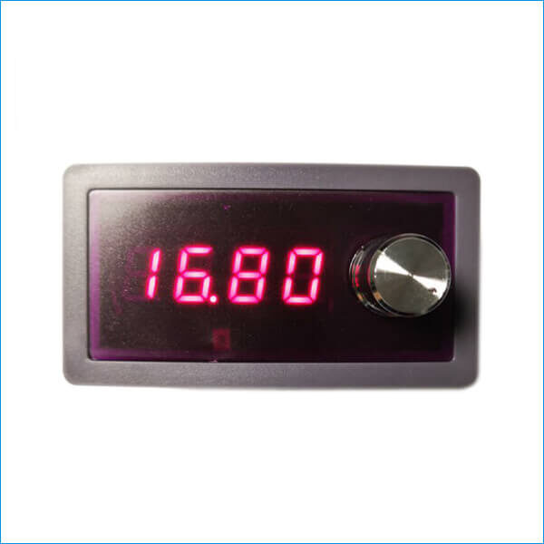
BRT 420LGPM 2-wire 4-20mA loop simulator set-point signal generator supports digital programming setting, current signal automatic output, 4-20mA current loop signal percentage display, parameters save, etc. functions. Its output range and display mode can be set through the button. It works with Siemens PLC and other PLCs, and also can be used in 3-wire 4-20mA simulation, 4-wire 4-20mA simulation by adding resistance. Low power consumption, stable output, it is an essential simplified current loop calibrator and tester instead of other expensive 4-20mA loop calibrator in industrial sites and labs.
Features and Benefits
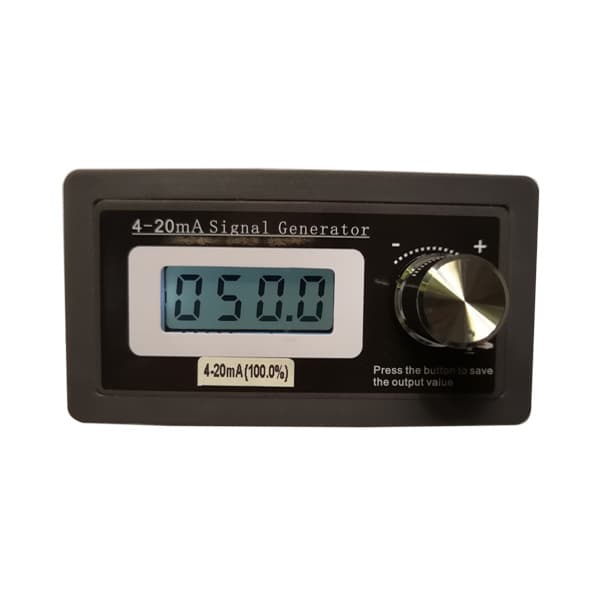
• LCD display with back light; display modes: 4-20mA current value, 0-100 (%) percentage, 0.0-50.0 (Hz), display mode is switchable via knob.
• 9 Segments programmable signal output in curves form.
• Using accurate digital rotary encoder, not potentiometer (the current generator with potentiometer is easily affected by temperature and humidity, resistance maybe change in operation).
• Signal output range: 4-20mA default, max. 3-21mA, output range is switchable and programmable.
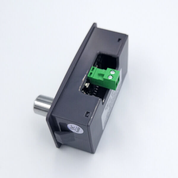
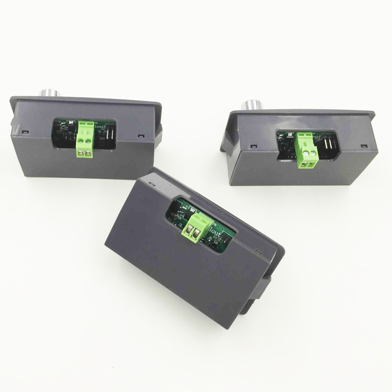
• Have reverse polarity protection (two-wire connection, no need to check positive or negative terminal, it can work properly without damages).
• High precision and linearity (display resolution “0.05”, two decimal points, actual output accuracy ±0.5%).
• Low power consumption, low heat, more stable output.
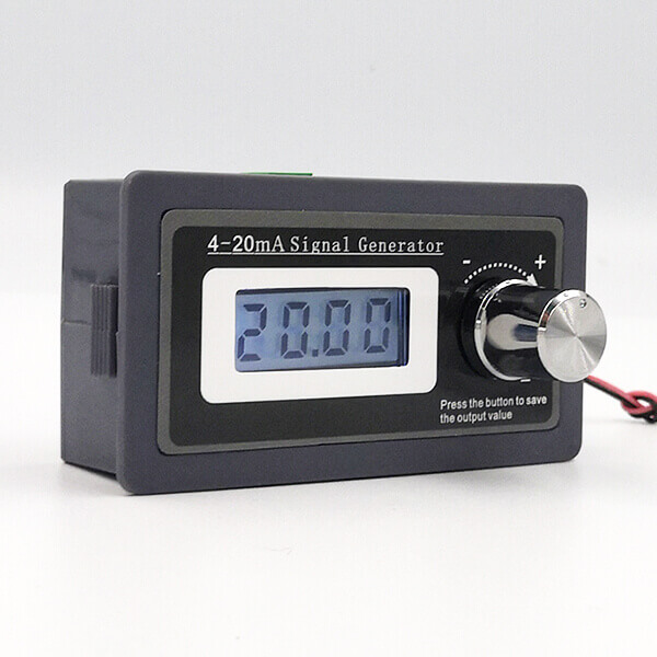
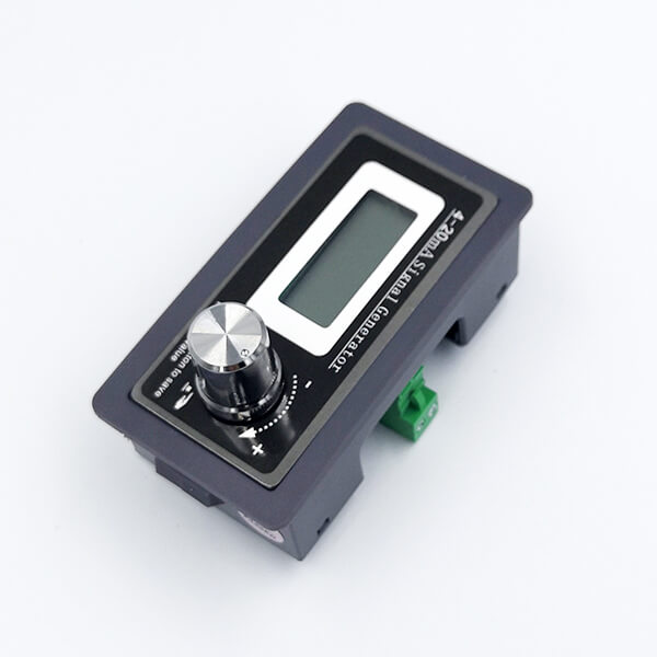
• Refined elegant shell, standard panel-mounted design, easy to do further integration.
4-20mA Loop Simulator Parameters
| Output current signal: | Default 4–20mA, max. 3mA to 21mA |
| Power supply voltage: | 15V to 30V |
| Sampling resistor: | 10Ω—500Ω |
| Display precision: | 0.01mA max. |
| Output precision: | ±0.5% |
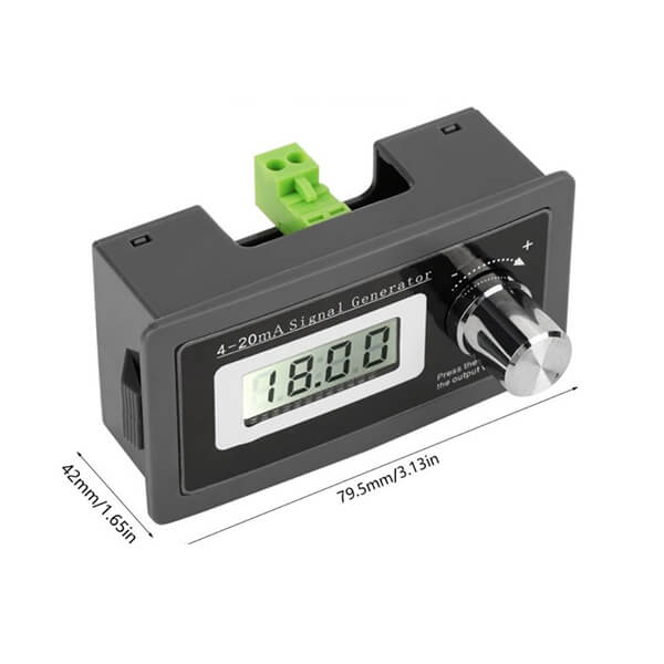
| Physical size (front): | 79.5 x 42mm |
| Physical size (back): | 72.5 x 39.5mm |
| Install panel /Panel cut-out size: | 77 x 40mm (±1mm error) |
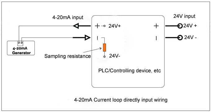
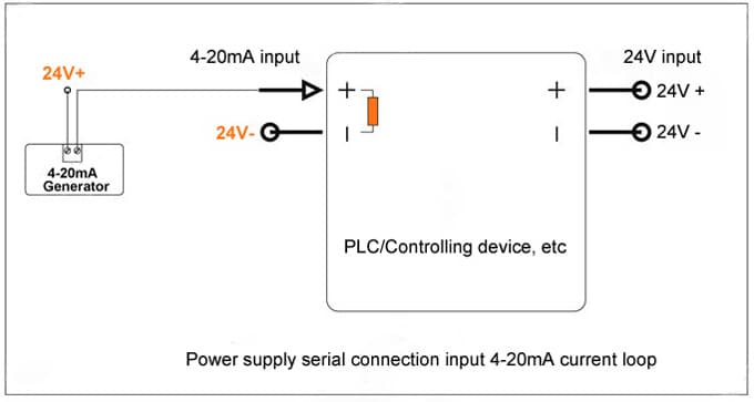
2-wire 4-20mA Simulation Output Wiring
(This 4-20mA signal generator connection does not have positive and negative polarity. 3-wire 4-wire application diagram is similar to that of 2-wire loop wiring circuit.)
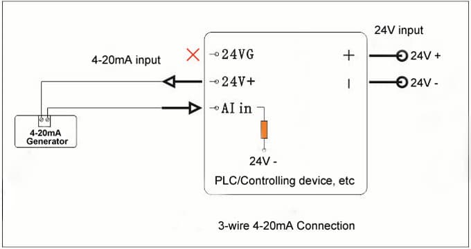
3-wire 4-20mA Calibration Wiring
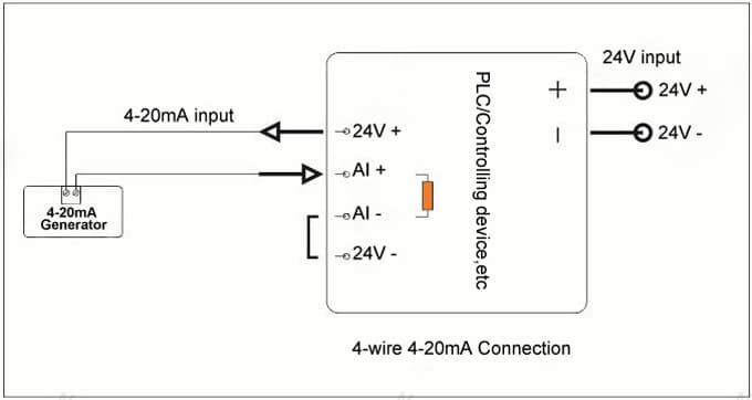
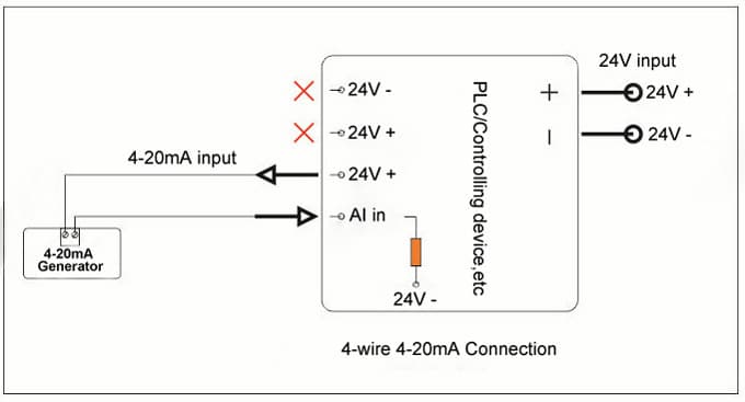
4-wire 4-20mA Calibration Wiring
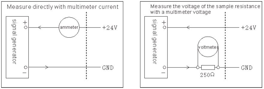
4-20mA Current Signal Measurement
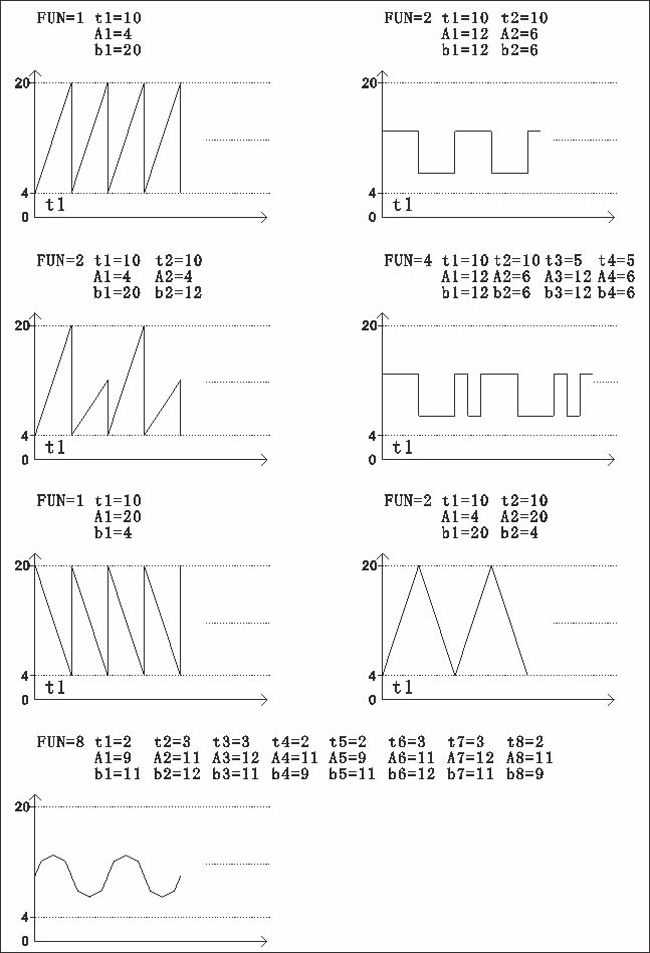
4-20mA Signal Automatic Output in Curves Form
Setting Steps
a) This signal generator has two operating modes: manual adjustment mode; Dynamic output mode;
b) Adjusting the output current in manual adjustment mode : rotate encoder knob, clockwise turn, current increases, counterclockwise turn, current decreases. In manual mode, there is two adjustment steps: fine adjustment step (default setting): 0.05mA step change, from 3mA to 21mA, the knob rotation angle is 18-turn. Rough adjustment step: 0.5mA step change, from 3mA to 21mA, the knob rotation angle is 1.8-turn.
c) In manual mode, saves the output value: short press the encoder knob, then release, the screen displays “…” . It indicates saving it successfully, and the output value of the next boot is the saved value; When debugging the device, we need to adjust the output value at random, so long as we don’t press down the adjusting knob, it remains the same value as we saved when we reboot.
d) Dynamic output mode: it is the automatic output of a programmable curve loop. Please contact us to get the detailed setting methods.
Note: Please note that no need to distinguish the positive terminal or the negative terminal of this two-wire 4-20mA loop simulator when you do wiring connection. The sign on the diagram is just for reference only.
Download User Manual:


Reviews
There are no reviews yet.